

FU1250-FU2550
HYDRAULIC DIVISION FU1250 & FU2550
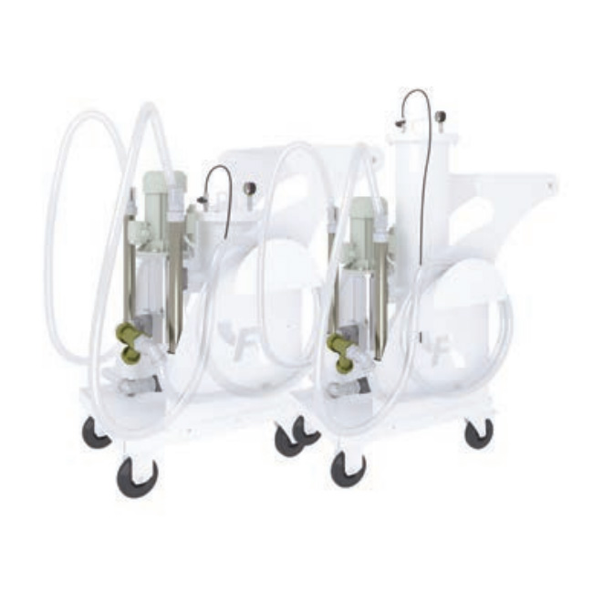
FU1250 & FU2550
Hydraulic oil transfer and filtration mobile unit
The unit is supplied complete with a Use and Maintenance Manual and it can be used only by
authorized operators, that have read and understood completely the Manual.
The FU units are CE certified
TECHNICAL INFORMATION
FU1250 & FU2550 1/4
SUPPORT FRAME AND FILTER
HOUSING:
Carbon steel, painted, mounted on 4 wheels (2 are lockable).
THREE PHASE ELECTRIC MOTOR: 1,1 kW, 4 poles, 230/440 V 50 Hz for FU1250
3 kW, 2 or 4 poles, 230/440 V 50 Hz for FU2550
PUMP PROTECTION: Y type filter, 500 µm.
OVERALL DIMENSIONS (LxPxH): 700 x 1.050x 1.250 mm for FU1250
700 x 1.050 x 1.400 mm for FU2550
WEIGHT: kg 155 approx for FU1250
kg 175 approx for FU2550
A filter element must be fitted in the filter housing before start: See page 3.
OPERATING TEMPERATURE RANGE: 0°C +80°C
FLUID COMPATIBILITY: Full with HH-HL-HM-HV (acc. To ISO 2943).
For use with other fluid please contact Filtrec Customer Service
(info@filtrec.it).
Viscosity: from 30 cSt to 1000 cSt
For use with other fluids please contact the FILTREC Customer Service
(info@filtrec.it)
FRAME
ELEMENT tested according to ISO 2941, 2942, 2943, 3968, 16889, 23181
ORDERING INFORMATION
1. FILTER SERIES
4. ELECTRIC MOTOR
6. SEALS
1. 2. 3. 4. 5. 6. 7.
FU 1250 4 T 040 B 01
FU
2. MODEL
3. ELECTRIC MOTOR
5. FLOW RATE 040 flow rate 40 l/min (FU12504T)
080 flow rate 80 l/min (FU25504T)
160 flow rate 160 l/min (FU25502T)
2 2 poles electric motor (FU2550 only)
4 4 poles electric motor
1250 fits 1x RU1250 filter element
2550 fits 1x RU2550 filter element
T three phase electric motor
B NBR
7. VERSION 00 STD version
FU1250 & FU2550 2/4
HYDRAULIC DIVISION FU1250 & FU2550
The filter element must be replaced:
1. When the oil transfer is completed (when used as oil transfer unit).
2. When the target cleanliness class is reached (when used as off line filtration unit); (more filter elements could be
necessary to reach it, depending on the oil volume to be cleaned and from the initial contamination level).
3. When both the differential pressure indicators show the red sector.
4. When a different filter media is required.
FILTER ELEMENT FITS FILTRATION
RU1250G03B FU1250 glassfiber ß4,5 µm (C) >1000
RU1250G10B FU1250 glassfiber ß12 µm (C) >1000
RU1250GW10B FU1250 glassfiber ß12 µm (C) >1000 +water absorber
RU2550G03B FU2550 glassfiber ß4,5 µm (C) >1000
RU2550G10B FU2550 glassfiber ß12 µm (C) >1000
RU2550GW10B FU2550 glassfiber ß12 µm (C) >1000 +water absorber
FILTER ELEMENTS
HYDRAULIC DIVISION FU1250 & FU2550
FU1250 & FU2550 3/4
OVERALL DIMENSIONS
1100
500 650
1250
700
1050
“FU1250**00”
1100
500 650
1250
700
1400
1050
“FU2550**00”
ELECTRIC DIAGRAM
HYDRAULIC DIVISION FU1250 & FU2550
FU1250 & FU2550 4/4
L1
L2
L3
PE
HYDRAULIC SCHEME
M
INLET
OUTLET
0.35 bar
6 bar
1
2
3
4
5
5
5
5
6
7
8
9
10
11
ITEM DESCRIPTION MODEL
FU12504T FU25504T FU25502T
1 Inlet flexible hose,dia,length, with
rigid ends TF-IN-42-5000 TF-IN-48-5000 TF-IN-60-5000
2 Suction filter “Y” type 1” ¼ Y filter 1” ½ Y filter 2” Y filter
3 Screw pump (l/min) with
integrated safety valve Screw pump 40 l/min Screw pump 80 l/min Screw pump 160
l/min
4 Electric motor TR_4P_kW1,1_V230/440 TR_4P_kW3_V230/440 TR_2P_kW3_V230/440
5 Sampling port Minimess type 1620 ISO228 G1/4"
6 Pressure gauge 213-53-63 0-16 bar G1/4” rad.
7 Visual clogging indicator 2,5 bar V02
8 Visual clogging indicator 5 bar V05
9 Air drain valve complete with
microhose ART1800
10 Check valve VU114-5PSI
11 Outlet flexible hose,dia,length,
with rigid ends TF-OUT-42-5000
COMPONENT LIST
CT80-rev.00-01/20
Technical information may change without notice
www.filtrec.com